


⚠️ Advanced Technical Content
Before proceeding: This guide assumes significant electronics expertise, microcontroller programming experience, and adequate workshop facilities. If you're researching whether to build or buy, start with:
→ Part 1: DIY vs. Commercial Systems Comparison
That comprehensive guide helps you make an informed decision about whether DIY construction or commercial systems better serve your needs.
This Part 2 guide is for committed DIY builders who have assessed the requirements and chosen to proceed with custom construction.
Introduction
In our previous DIY Automatic Chicken Door article, we gave you access to detailed plans for building the wooden cabinet, door and the controller housing for your auto chicken door.
In this article, our intent is to provide information and designs for the electronics-based components in your DIY Auto Chicken Door.
Overview
You learn about a solid and simple solution to opening and closing your coop door. You’ll also learn about the tools, materials and parts which you will need.
Our approach is to provide a modular DIY approach to building your own auto chicken door. The information which follows, and the associated design files will provide a solid foundation for the electronic and hardware components of your DIY Automatic Coop Door solution.
See our DIY Automatic Chicken Door – Part 1 article for information and free plans to build the wooden parts.
The electronics do require some special tools including a micro-controller programmer. Coop Tender® offers most of the parts you might need, including a pre-built and tested automatic chicken door controller.
At the end of the article, you’ll have access to our Jumpshare cloud file sharing folder with all the files and documents.
Auto Chicken Door Components
As mentioned in our previous post, there are basically 3 major components to an automatic chicken door.
- Physical Door and Frame: Provide an opening during the day and solid entrance barrier at night.
- Door Drive Mechanism: How the door will be operated to open and close the entrance
- Door Controller and Associated Hardware: The coop door brains which determine when to open and close the door, but also to activate the Door Drive Mechanism to do so. Associated Hardware includes wire, connectors, power, etc.
In an ideal solution, each of the 3 components will work together to provide a durable operating experience. Physical dimensions, precision woodworking, drive mechanism and electronics working together within designed specifications to provide a durable, long lasting solution.
Auto Chicken Door Electronics Design Considerations
The size and weight of the door has the most impact on overall electronics design considerations. Each of the other components are designed with these and other physical operational aspects in mind.
If you built your DIY Auto Chicken Door with these free diy chicken door plans (https://jumpshare.com/v/fizEpLxfLpnAKCfwfgdX?b=Q1UiEKKeAlqIw4xtPthA), we’ve got a good basis for the physical characteristics of the door mechanism (i.e. size and weight).
Chicken Door Controller
With the physical and mechanical aspects of your automatic chicken door in mind, we can begin to search for the ideal solution to operate it automatically.
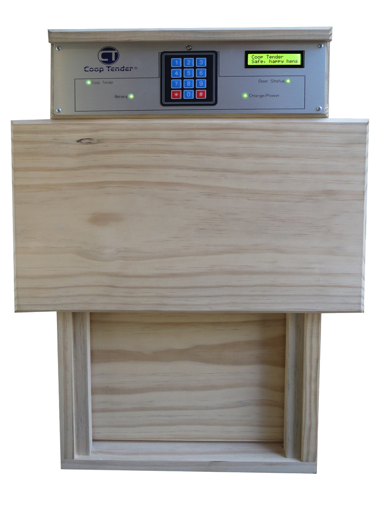
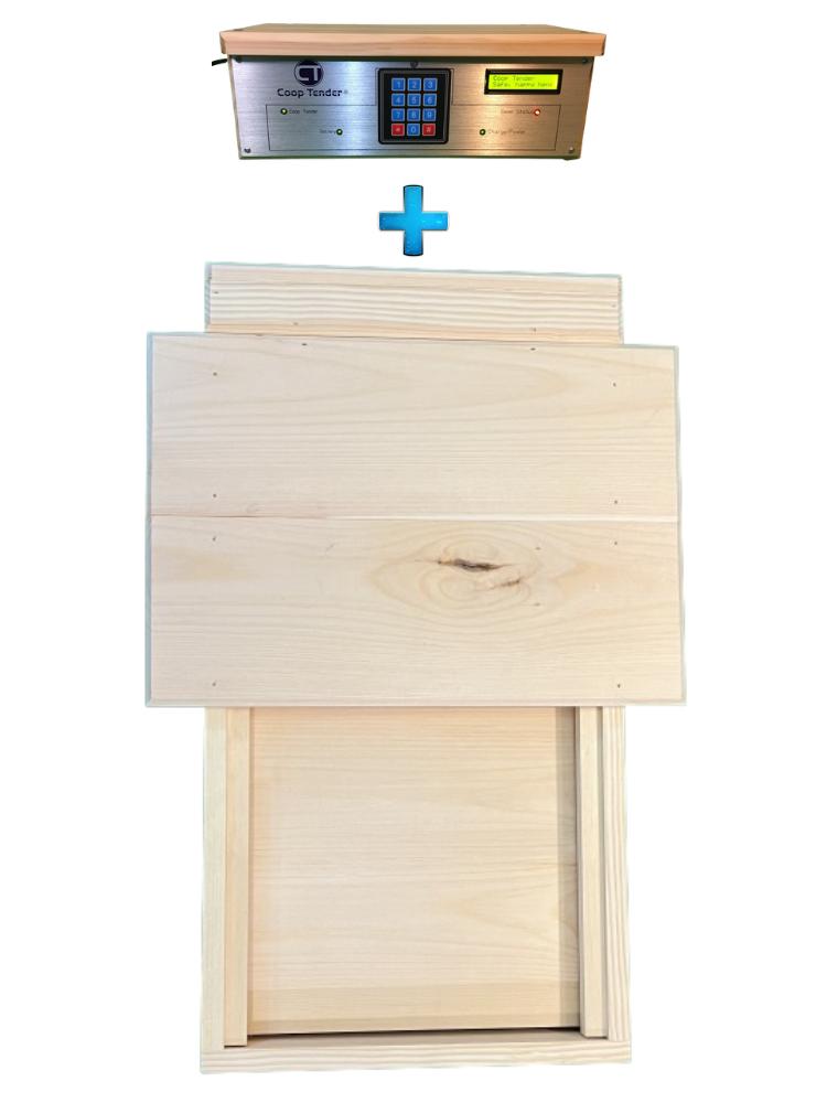
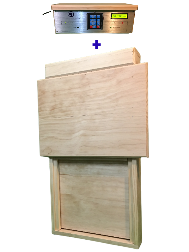
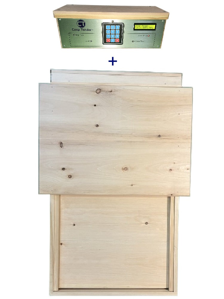
Coop Tender® can help if you’d rather not delve into the highly technical aspects of the door controller. Our Automatic Chicken Coop Door Control Panel Assembly is plug-and-play. All you need to do is follow the wiring diagram for the 12-pin connector by connecting the motor, limit switches and power. It’s also Internet Wi-Fi Enabled. This means that the firmware has been programmed to communicate with an IoT based Coop Door Wi-Fi Micro-Controller Module. So, connecting your door to the Internet is also plug-and-play.
If you’re interested in working with electronics, read on.
Basic Requirements
Before jumping in and slapping a solution together, let’s think about the ideal solution.
Low Power Consumption: Especially if you plan to operate with solar, the solution should consume no more than about 50 milliamps of dc power on average. This is low enough to power with a 12 Volt 5 Amp Hour SLA battery and 10 watt solar panel.
A Display: Display key operational parameters in human readable format.
LED Light Indicators: Very helpful at night to provide visual color status indicators – warnings, battery, power, door status. No need to pull your boots and coat on during a cold winter night to check the door.
Human Interface: Some method which allows basic “programming” and operational control using an input device such as a switch or array of switches (e.g. matrix keypad).
Temperature: There are several beneficial control aspects to knowing the environmental temperature. In northern climates, temperature can be used to determine whether to open the door or not. Chickens won’t go out when it’s too cold. Keeping the door closed during sub-freezing temperatures helps to keep your chickens warmer and safer.
Temperature readings can also be used to activate supplemental ventilation in your chicken coop.
Battery Charge Controller: It never hurts to have a backup power supply to operate the door if electricity fails. A battery charge controller is essential if you want to operate your door using solar energy.
Wi-Fi Network Integration: Although maybe not essential. Connecting IoT (Internet of Things) technology to your automatic chicken door has many benefits. Door Status SMS alerts, monitor and control via the Internet as examples.
Electronics Design Concept
We now translate our requirements into an Electronics design concept. We’ll discuss the major components from an electronics perspective. You will also have access to the electronics parts BOM which contains manufacturer and supplier part numbers at the end of the article.
It soon becomes apparent that we can use a low cost micro-controller IC Chip and program it to process and control sensor signals. We’re a fan of the ATMega328 chip found on many of the Arduino prototyping development boards. It’s simple to transition from prototyping using the development board to PCB circuit design.
As you build your prototype, you update your firmware code to incorporate and process each I/O component. For Example: Reading, storing and incorporating the temperature as a criteria comparator for temperature-based operations. And displaying messages on the LCD Screen.
At some point, you will realize that your micro-controller does not have enough digital input/output pins to implement all the functionality you want. No worries. Microchip Technology manufactures an I/O Expander IC Chip, the MCP23008-E/P which solves the problem. This chip can be used to “offload” basic digital I/O operations such as turning on a LED.
You’re going to need something to regulate the voltage supplied to the on-board components and IC chips. Micro-electronics tend to like stable voltages. Linear voltage regulators like the LM7805 are simple to implement and are very durable. The only downside to linear regulators is that they are not as efficient as some of the modern DC-DC buck regulators on the market, but they do the job well.
Linear voltage regulators like the LM317 are a perfect solution to providing battery charge capabilities to your solution. When implemented as a current regulator, it takes only a few parts.
One of the most critical components for your DIY Automatic Chicken Door controller is a way to turn the motor both ways to open and close the door. With a permanent magnet DC motor, reversing the polarity of the voltage to the motor will reverse its direction. Texas Instruments makes a Half Bridge (H-Bridge) IC chip (Part #: SN754410NE) which can be used to digitally control the polarity of the voltage which gets sent to the motor. This chip is rated to output up to 1 Amp. That’s quite a bit of power. Ensure that your motor draws less than 1 Amp or you’ll end up damaging the chip.
Limit Switches: The best way to sense door position is to use limit switches. Limit switches have a triggering mechanism which will open or close the switch. Your circuit will have resistors so that you can tell which switch is activated by the analog voltage value which is read by the micro-controller. Although there are mechanical limit switches, we believe that ones which operate on magnetic principles are the most durable.
Firmware Design
Since we have decided to use a micro-controller in our electronics design, we’re going to need to write some code to make things work.
The best way (IMHO) to do this is with iterative design and code implementation. Known the big picture and end goal, prototype and test each component one at a time. You can do this using a serial debugger at first, until you have the option of sending messages to the LCD panel for debugging purposes. Serial debugging does offer more flexibility and ease in setting up messages to write out.
If you’re going to program your own firmware, take some time to learn about the environment, or tool chain, you will be using. Knowing the basics will go a long way towards developing a solid solution.
You can find many examples and a lot of support for Arduino based prototyping. There are many open source firmware libraries available that you can use to easily integrate various sensors and components into your overall design.
If you end up using an Arduino to prototype your design, you will also be working within the confines of the Loop() architecture. On these devices, you have code for setup which runs only when the device starts up and then all other processing basically happens in loop() which runs infinitely.
You will likely soon find that the loop() architecture is making your code “clunky”. If all processing is put into a list of functions called from loop, you’re likely to encounter issues with delays incurred by this linear type of firmware development.
If you’re familiar with Finite-state machine implementations, then this would be a good application for it. If not, this Wikipedia article provides a good foundation behind the principle(https://en.wikipedia.org/wiki/Finite-state_machine). You can find code examples online to help implement your own state machine architecture into the firmware and it is highly recommended.
Overall Architecture Design
When designing and prototyping your system, the tools you use can help to simplify the process or provide valuable functionality.
For designing PCBs and schematics, there are several software solutions available such as Eagle and KiCad, which are probably the best known. If you don’t have one, look at Fritzing. It’s basically an open source PCB design solution and it works well. You can use it to export the files necessary to have your PCB manufactured. For this type of project, it really does not make sense to try to etch and drill your own board. Home etching is ok for simple PCBs, but not so good for many of the thin traces you’ll have on your PCB. If you are designing a Thru Hole component PCB, then there are lot of holes which will need to be drilled. Both of these are best handled by the professionals. The good thing is that there are currently many PCB manufacturing resources available at your fingertips. China tends to dominate the market for low cost PCB production of your prototype. There are local PCB manufacturers available, but you’ll likely find that “one off” PCBs are quite costly.
For firmware design and development, Arduino does have an IDE which you can use. Most likely, you’ll find that things get a bit cumbersome moving between sections of your code. A plug-in is available for Microsoft Visual Studio development environment which helps to simplify code management. The plug-in is also available for other major development environments if Microsoft is not your thing.
BOM Parts List
We’re getting towards the end of this article. We hope that the information you have received is helpful in some way.
At the end of this article, you will have access to a shared folder which also contains a sample PCB for your DIY Automatic Chicken Door Controller. The PCB was used in earlier models of Coop Tender® Automatic Chicken Doors and uses Thru Hole Technology (THT), so does not require special reflow equipment needed for Surface Mount Technology (SMT) PCBs.
The Parts List (a.k.a. BOM – Bill of Materials) which follows provides you with a list of the parts which are needed to build the door controller circuit board PCB. The download file has more details. The parts costs are current parts costs as of the time of this writing. Most of the parts can be obtained from Digi-Key. The Digi-Key part numbers and other supplier part numbers are in the parts file.

This PCB design incorporates all of the design requirements which we discussed earlier:The schematic can be used so that you are programming each component to the correct I/O pins of the micro-controller and I/O expander.
DIY Automatic Chicken Door Electronics BOM Parts List
| Part# | Qty | Manufacturer | Mfg Part | Description | Cost | Ext. Cost |
| 1 | 1 | Coop Tender | CT168 | Metal Faceplate | $24.99 | $24.99 |
| 2 | 1 | Coop Tender | CT181-THT | Coop Tender PCB | $9.99 | $9.99 |
| 3 | 1 | Microchip Technology | ATMEGA328-PU | IC MCU 8BIT 32KB FLASH 28DIP | $1.96 | $1.96 |
| 4 | 1 | Microchip Technology | MCP23008-E/P | IC I/O EXPANDER I2C 8B 18DIP | $1.05 | $1.05 |
| 5 | 1 | Texas instruments | SN754410NE | IC HALF-H DRVR QUAD 16-DIP | $2.52 | $2.52 |
| 6 | 1 | Various | DS1307 RTC | DS1307 RTC Module | $7.99 | $7.99 |
| 7 | 1 | Texas Instruments | LM7805CT/NOPB | IC REG LINEAR 5V 1A TO220-3 | $1.54 | $1.54 |
| 8 | 1 | ON Semiconductor | LM317BTG | IC REG LIN POS ADJ 1.5A TO220AB | $0.65 | $0.65 |
| 9 | 1 | Mean Well USA Inc | EPS-15-15 | AC/DC CONVERTER 15V 15W | $8.53 | $8.53 |
| 10 | 1 | Various | 1602 LCD | LCD Module | $7.00 | $7.00 |
| 11 | 1 | Adafruit | 419 | Membrane 3x4 Matrix Keypad | $7.36 | $7.36 |
| 12 | 7 | Harwin Inc | M20-1160042 | CONN SOCKET 22-30AWG CRIMP GOLD | $0.10 | $0.70 |
| 13 | 10 | BusBoard Prototype Systems | SA180x24 | SA180 Adhesive Standoffs | $0.80 | $8.00 |
| 14 | 2 | Various - Schmartboard, Inc. | 920-0172-01 | CONN HEADER VERT 40P 2.54MM 3PC | $2.50 | $5.00 |
| 15 | 7 | Various - Vishay BC Components | K104K15X7RF5TH5 | CAP CER 0.1UF 50V X7R RADIAL | $0.23 | $1.61 |
| 16 | 1 | Various - Keimet | C330C334K5R5TA | CAP CER 0.33UF 50V X7R RADIAL | $0.83 | $0.83 |
| 17 | 1 | Various - Nichicon | UVR1H470MED1TD | CAP ALUM 47UF 20% 50V RADIAL | $0.28 | $0.28 |
| 18 | 1 | Harwin Inc | M20-1060200 | CONN RCPT HSG 2POS 2.54MM | $0.16 | $0.16 |
| 19 | 2 | Harwin Inc | M20-1060400 | CONN RCPT HSG 4POS 2.54MM | $0.20 | $0.40 |
| 20 | 4 | Harwin Inc | M20-1060600 | CONN RCPT HSG 6POS 2.54MM | $0.27 | $1.08 |
| 21 | 1 | Harwin Inc | M20-1060800 | CONN RCPT HSG 8POS 2.54MM | $0.36 | $0.36 |
| 22 | 1 | Harwin Inc | M20-1061000 | CONN RCPT HSG 10POS 2.54MM | $0.44 | $0.44 |
| 23 | 2 | Various - Bel Fuse Inc. | 5MF 1.5-R | FUSE GLASS 1.5A 250VAC 5X20MM | $0.21 | $0.42 |
| 24 | 1 | All Electronics | HS-7139 | Clip on Heat Sink | $0.99 | $0.99 |
| 25 | 1 | Mill-Max Manufacturing Corp. | 110-99-628-41-001000 | CONN IC DIP SOCKET 28POS TINLEAD | $1.35 | $1.35 |
| 26 | 1 | Mill-Max Manufacturing Corp. | 110-99-318-41-001000 | CONN IC DIP SOCKET 18POS TINLEAD | $0.88 | $0.88 |
| 27 | 1 | Mill-Max Manufacturing Corp. | 110-99-316-41-001000 | CONN IC DIP SOCKET 16POS TINLEAD | $0.78 | $0.78 |
| 28 | 4 | All Electronics | HLED-5 | Clips for T1 (3mm) LEDs | $0.25 | $1.00 |
| 29 | 4 | All Electronics | LED-67 | T1 Red/Green LED 3 Legs | $0.35 | $1.40 |
| 30 | 1 | Littlefuse Inc. | 57150-000 | MAGNET 1.125"L X 0.259"W PLASTIC | $2.66 | $2.66 |
| 31 | 2 | Littlefuse Inc. | 59150-010 | SENSOR REED SW SPST-NO W LEADS | $2.88 | $5.76 |
| 32 | 1 | Advanced Photonix | PDV-P8103 | PHOTOCELL 16-33KOHM | $0.89 | $0.89 |
| 33 | 1 | Bourns Inc. | 3352E-1-103LF | THUMBWHEEL POT 10K OHM 0.5W TOP | $1.85 | $1.85 |
| 34 | 1 | All Electronics | LCAC-60 | 6' BLACK 18/3 IEC DETACHABLE POWER CORD | $3.50 | $3.50 |
| 35 | 1 | URBEST | JB | Male Power Socket 10A 250V Inlet Module Plug 5A Fuse Switch | $7.99 | $7.99 |
| 36 | 2 | Stackpole Electronics Inc | RNMF14FTC220R | RES 220 OHM 1/4W 1% AXIAL | $0.10 | $0.20 |
| 37 | 1 | Stackpole Electronics Inc | RNMF14FTC22R0 | RES 22 OHM 1/4W 1% AXIAL | $0.10 | $0.10 |
| 38 | 3 | Stackpole Electronics Inc | RNMF14FTC4K70 | RES 4.7K OHM 1/4W 1% AXIAL | $0.22 | $0.66 |
| 39 | 1 | Stackpole Electronics Inc | RNMF14FTC3K30 | RES 3.3K OHM 1/4W 1% AXIAL | $0.10 | $0.10 |
| 40 | 3 | Stackpole Electronics Inc | RNMF14FTC10K0 | RES 10K OHM 1/4W 1% AXIAL | $0.10 | $0.30 |
| 41 | 4 | Stackpole Electronics Inc | RNF14FTD1K00 | RES 1K OHM 1/4W 1% AXIAL | $0.10 | $0.40 |
| 42 | 5 | Stackpole Electronics Inc | RNMF14FTC2K00 | RES 2K OHM 1/4W 1% AXIAL | $0.10 | $0.50 |
| 43 | 2 | Vishay BC Components | MBB02070C4708FRP00 | RES 4.7 OHM 0.6W 1% AXIAL | $0.22 | $0.44 |
| 44 | 10 | Stackpole Electronics Inc | RNMF14FTC680R | RES 680 OHM 1/4W 1% AXIAL | $0.10 | $1.00 |
| 45 | 4 | On Shore Technology Inc | OSTTE020104 | TERM BLK 2POS SIDE ENT 3.5MM PCB | $0.73 | $2.92 |
| 46 | 2 | Vishay Semiconductor Diodes Division | 1N5819-E3/54 | DIODE SCHOTTKY 40V 1A DO204AL | $0.46 | $0.92 |
| 47 | 1 | DGZZi | TSDS18B20-1M | Digital Temperature Probe | $7.59 | $7.59 |
| 48 | 1 | ON Semiconductor | PN2222ATA | TRANS NPN 40V 1A TO92 | $0.25 | $0.25 |
| 49 | 30 | Various | Various | F-F 1P 20cm Connector Wires (30) | $0.14 | $4.20 |
| 50 | 4 | All Electronics | 1125 | 1/4 Inch Quick Connect Female | $1.00 | $4.00 |
| 51 | 6 | All Electronics | WN-11 | Waterproof Wiring Nuts Blue 22-12 AWG | $1.30 | $7.80 |
| 52 | 3 | All Electronics | 20BK-100S | 20 Ga Black Hook-up Wire solid 100' | $10.00 | $30.00 |
| 56 | 1 | All Electronics | Con-1200 | 12-Pin Connector | $3.70 | $3.70 |
| 58 | 1 | All Electronics | HSB-24B | Heat Shrink Tubing Assortment | $3.95 | $3.95 |
| 59 | 4 | Wire Ties | $0.00 | |||
| 60 | 2 | Stackpole Electronics Inc | RNMF14FTC10R0 | RES 10 OHM 1/4W 1% AXIAL | $0.10 | $0.20 |
| 61 | 1 | All Electronics | FHP-72 | Inline GMA Fuse Holder | $0.90 | $0.90 |
| 62 | 1 | Stackpole Electronics Inc | RNMF14FTC200R | RES 200 OHM 1/4W 1% AXIAL | $0.10 | $0.10 |
| 63 | 4 | JST Sales America Inc. | SVH-21T-P1.1 | CONN SOCKET 18-22AWG CRIMP TIN | $0.11 | $0.44 |
| 64 | 7 | Harwin Inc | M20-1160042 | CONN SOCKET 22-30AWG CRIMP GOLD | $0.10 | $0.70 |
| 65 | 1 | Visual Communications Company - VCC | CLR_301_CTP | LENS CLEAR PANEL MOUNT SNAP-IN | $0.73 | $0.73 |
| 66 | 1 | Visual Communications Company - VCC | SPC_125 | CLIPLITE SPACER | $0.50 | $0.50 |
| 67 | 1 | Various | 12 Volt Gear Motor | $29.99 | $29.99 | |
| 68 | 1 | Baden Steelbar and Bolt Corp | 5/8-8 Acme | 5/8-8 Acme threaded Worm drive assembly | $29.99 | $29.99 |
| Totals | 176 | $254.49 |
DIY Auto Chicken Door Electronics Plans
If you want to delve into the electronics engineering aspect of your DIY Automatic Chicken Door, you can access all the design files on our Jumpshare file sharing site.
The shared folder contains:
- DIY Automatic Chicken Coop Door Instructions PDF document
- PCB Layout PDF Document
- PCB Layout Gerber files
- Schematic
- Parts List (and PCB Cross Reference)
- DIY Automatic Chicken Door Electronics Plans
Secure HTTPS:
Leave a comment