
Coop Tender Automatic Door Complete Installation & Setup Guide
Coop Tender Automatic Door
Complete Installation & Setup Guide
Professional-Grade Protection for Your Flock
📋 Table of Contents
⚠️ SAFETY FIRST - READ BEFORE STARTING
CRITICAL: Ensure door controller is unplugged and power switch is in the OFF position prior to installation.
Power Switch Position:
- O = Off
- - = On
Made in U.S.A. This device complies with Part 15 of the FCC Rules. Operation is subject to the condition that this device does not cause harmful interference.
🔋 Step 1: Optional Solar / Backup Battery Installation
If you purchased a solar system or backup battery, install it before mounting the door.
Battery Installation Steps:
- Remove controller cover: Unscrew the 4 screws from the top of the door controller
-
Connect the battery:
- Red wire (with inline fuse holder) = Positive (+)
- Brown or Gray wire = Negative (-)
- Position battery: Place battery in the open area in the left portion of the controller
- Replace cover: Put controller top back on and secure with the 4 screws
🚪 Step 2: Door Installation
Step 2.1: Cut Opening Based on Your Model
| Model | Door Opening Dimensions | Controller Dimensions |
|---|---|---|
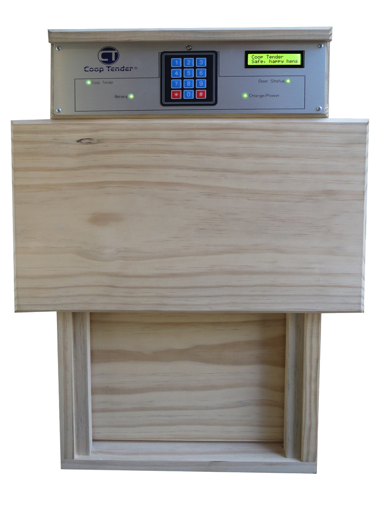
| CT-003 Standard | 13½" wide × 26½" high | Built into door |
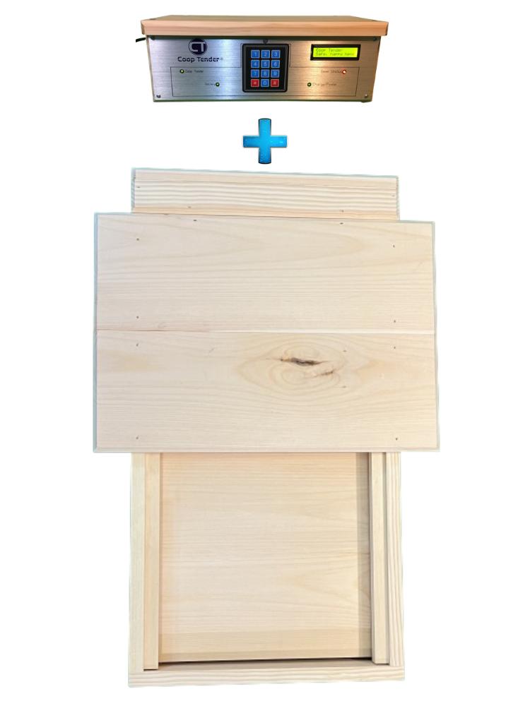
| CT-003 w/ Separate Controller | 13½" wide × 24¼" high | 13½" wide × 5" high |
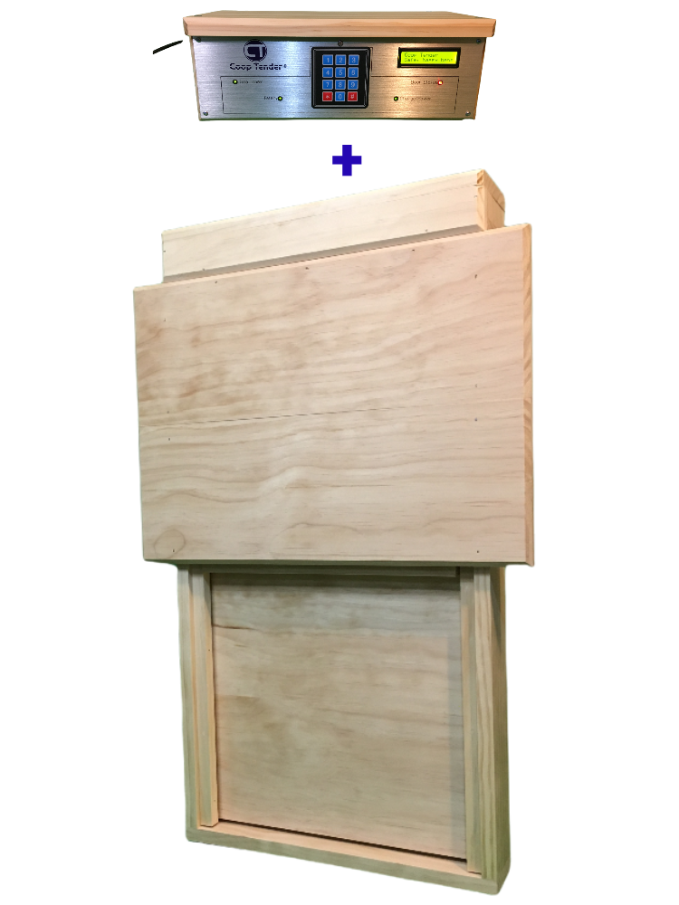
| CT-004 Large | 15" wide × 28¼" high | 13½" wide × 5" high |
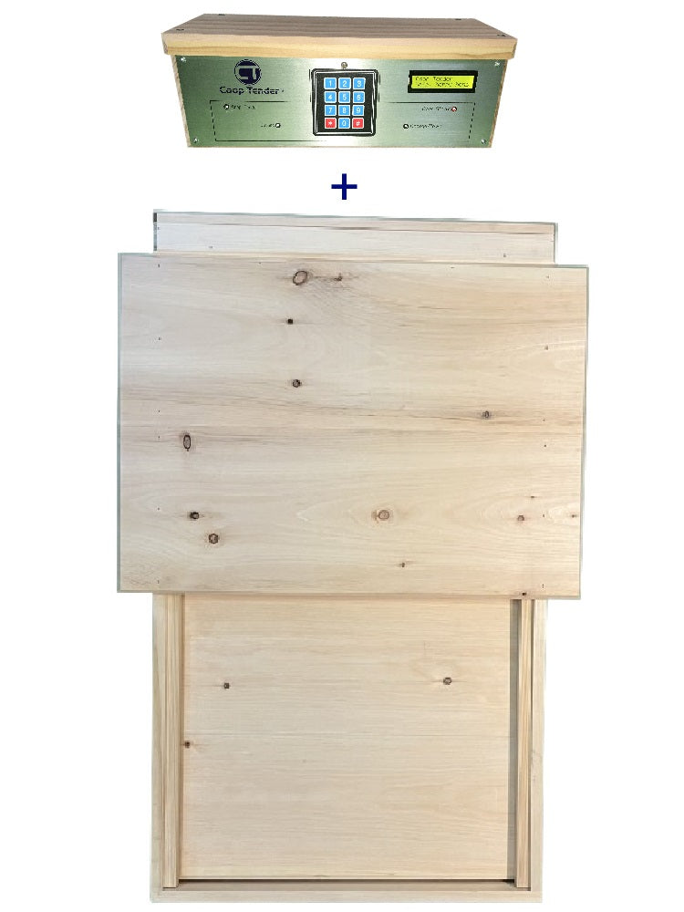
| CT-005 Extra Large | 17½" wide × 34¼" high | 13½" wide × 5" high |
| CT-006 Small | 11" wide × 20" high | 13½" wide × 5" high |
| CT-007 Certified Humane | 24" wide × 41½" high | 13½" wide × 5" high |
Step 2.2: Install Door Unit
- Position door: Slide the door unit into the cutout you created
- Orient correctly: The control panel faces the outside of your chicken coop
- Secure door: Using the 4 included screws, screw the door to the doorway through the mounting panel holes
- Connect power: Plug the power cord into an electrical outlet and into the back of the Coop Tender controller
- Power on when ready: Turn the power switch to the ON position when you're ready to automatically control your door
☀️ Step 3: Optional Solar Panel Installation
Enough wire is provided to mount your solar panel to the front of your door or nearby. If you need more distance, you can extend the wire.
Step 3.1: Wire Extension (If Needed)
If the supplied wire isn't long enough for your desired solar panel location:
- Splice (add) your desired length of 20 AWG or thicker wire between the solar panel wires and the controller wires
- Use wire nuts to connect the wires securely
- Apply silicone to the wire nut connections to weatherproof them
- Solar Panel RED ➔ Your Extension Wire RED ➔ Controller RED
- Solar Panel BLACK ➔ Your Extension Wire BLACK ➔ Controller BLACK
Step 3.2: Solar Panel Connection
⚠️ CRITICAL: Only switch the solar panel ON after the battery has been installed and the door has been switched on.
Step 3.3: Solar Panel Mounting
Mounting Options:
Option 1: Purchase Mounting Hardware
- Search Amazon.com for "solar panel mounting bracket"
- Various brackets and stands available inexpensively
- Choose weather-durable materials suitable for outdoor use
Option 2: DIY Mounting
- The solar panel frame has 4 mounting holes on the back
- Use outdoor weather-durable wood, plastic, or metal pieces
- Attach extensions using machine screws, nuts, and washers through the frame holes
- Mount the extended pieces to your desired location
Option 3: Simple Hanging Method
- Insert two screws into your mounting surface
- "Hang" the panel using two of the frame holes
- Use adhesive caulk to further secure the panel
🌞 Optimal Solar Panel Positioning
For Most U.S. Locations:
- Direction: Face TRUE SOUTH
- Angle: 10-30 degrees (depends on your latitude)
- Minimum: Position to get as much afternoon sun as possible
🎛️ Step 4: Optional Mountable / Separate Controller Installation
For models with a separate controller (CT-003 with separate controller, CT-004, CT-005, CT-006, CT-007):
Separate Controller Installation:
- Route cable: Run the grey cable from the controller to the 5-pin connector on the door
-
Connect: Plug the connectors together
- Connectors only fit one direction
- Look for tabs on each connector to align correctly
- Press ends together until connectors lock
- Position temperature probe: Route the temperature probe to your desired monitoring location
-
Mount controller: Choose one of these mounting options:
- Flat surface: Mount to a shelf using included screws
- Wall mount: Use brackets to secure to wall
- Through-wall: Create a 13½" wide × 5" high cutout to mount through an exterior coop wall
⌨️ Step 5: Keypad Interface & Programming
Menu Navigation Controls:
-
[2]= Scroll UP -
[4]= BACK -
[6]= SELECT -
[8]= Scroll DOWN
To activate menu: Press any number button
Entering Numeric Values:
- Number keys function for numeric entry (not navigation)
- Menu automatically advances cursor to next digit
- Menu automatically accepts entry after all digits entered
-
[*]key = Move cursor back one position -
[#]key = Accept the setting value shown on display
📡 Step 6: WiFi Module Setup (Optional)
The Coop Tender Internet WiFi Module uses BLE (Bluetooth Low Energy) to connect to your local WiFi network.
Your WiFi Credentials:
Customer ID: Your Order Number (looks like CTXXXXXX)
You'll need this Customer ID when signing into the Universal Web App for the first time.
Step 6.1: Connect WiFi Module
- Power off: Switch door and solar panel (if installed) OFF
- Connect module: Insert the two ends of the 4-wire connectors together until they lock
- Enable Bluetooth: Ensure Bluetooth is enabled on your smartphone
Step 6.2: Download & Run Setup App
- Download the Coop Tender WiFi Setup app
- iOS: Search App Store for "Coop Tender WiFi"
- Android: Search Google Play for "Coop Tender WiFi"
- Launch the app after download
- Tap Connect WiFi Module
- Select your WiFi network, then Continue
- Enter network credentials (password), then Save
Step 6.3: Verify Connection
WiFi Module Status Lights:
- Blinking green → Connecting to WiFi network
- Blinking cyan → Connecting to Internet Cloud services
- Breathing cyan → ✅ Connected successfully!
Step 6.4: Mount WiFi Module
- Use the 2 included mounting screws
- Mount on top of controller or nearby location
- Important: Position so metal faceplate is NOT in direct line between module and WiFi router
- Best location: On top of or above the door unit
Step 6.5: Access Universal Web App
- Navigate to: ctwifi.cooptender.com
- Sign in using:
- Google account
- Facebook account
- LinkedIn account
- Create custom account
- First-time login: Enter your Customer ID (order number) when prompted
- Create home screen icon for easy access
🔌 Step 7: Accessory Control Module Setup (Optional)
Automatically or manually control lights, ventilation, and heat in your chicken coop from anywhere in the world.
Accessory Module Features:
- Two light circuits: Control based on ambient light or schedule
- Ventilation control: Temperature-based fan operation
- Heat control: Temperature-based heating (optional)
- Internet control: Requires WiFi Module for remote access
Step 7.1: Install Accessories
- Install lights and vent fans in desired locations
- Run wires from 12V accessories to the Accessory Control Module
- Connect positive (+) and negative (–) wires to appropriate screw connectors
Step 7.2: Optional Heat Control
- Position heater in desired location
- Use extension cord if heater cord is too short (ensure proper amp rating)
- Plug heater into AC outlet on Accessory Control Module
⚠️ Heater Safety: Ensure extension cord is rated to handle the heater's current load (typically 1500W / ~10 Amps @ 120V AC)
Step 7.3: Connect & Mount Module
- Plug Accessory Module connector into corresponding WiFi Module port
- Plug Accessory Module power cord into AC electrical outlet
- Mount module to wall using included screws (within 1 foot of WiFi Module)
Step 7.4: Configure via Web App
- Log into Coop Tender Universal Web App at ctwifi.cooptender.com
- Tap the gear icon next to your door listing
- Expand Accessory Module settings by tapping the plus sign
- Configure each accessory (lights, fan, heat) with desired settings
🦊 Step 8: Predator Motion Detector Setup (Optional)
The Coop Tender Predator Motion Sensor automatically arms when the door closes and alerts you of potential threats.
How Predator Alert Mode Works:
- 🚨 Module lights flash red for 30 seconds
- 💡 Activates Security Light for 1 minute (requires Accessory Module)
- 📧 Sends alerts via SMS and Email
Detection Range:
- Distance: Up to 5 meters (~16 feet)
- Coverage: 100° horizontal × 82° vertical
- Temperature Range: -20°C to 60°C (-3°F to 140°F)
Step 8.1: Install Detector
- Height: Mount 1-3 feet above ground level
- Direction: Point sensor AWAY from coop (watching for approaching predators)
- Location: Choose area not exposed to excessive dirt and debris
- Mounting: Use 2 included screws to secure module
Step 8.2: Connect to WiFi Module
- Route cable to inside of coop
- Connect to cable connector labeled "Predator Motion" on WiFi Module
- Connector only fits one way - match the connector shapes
🔧 Maintenance Schedule
Regular Maintenance Keeps Your Door Running Smoothly
Maintenance Frequency:
- Standard flocks: Annually
- Densely populated coops: Every 6 months
- Dusty environments: Every 6 months
Worm Drive Cleaning Procedure:
Over time, dirt and feather particles accumulate on the worm drive (Acme threaded rod), making it harder for the motor to operate.
- Remove back cover from door unit
- Spray liberally with WD-40 on the worm drive (long metal screw)
- Open and close the door a couple of times
- Wipe the drive clean with a cloth or paper towel
- Repeat steps 2-4 as needed until drive is clean
- Re-install back cover
Optional: Apply Lubricant
If you hear "chatter" after cleaning, you can apply a small amount of lubricant:
- Options: Lithium grease, beeswax, or paraffin wax
- Application: Run a small, thin strip along the length of the worm drive
- Distribution: Open and close the door to allow the drive nut to work the lubricant into the threads
⚠️ Important: Do NOT over-grease the worm drive. Too much grease attracts dirt and causes buildup. A thin strip is sufficient.
Additional Maintenance Tasks:
- Check battery: Test backup battery voltage annually (should be 12V+)
- Clean solar panel: Wipe dust and debris from solar panel surface quarterly
- Inspect wiring: Check for rodent damage or wear on all cables
- Test manual override: Verify manual operation works in case of power failure
- Clean sensors: Wipe light sensor and temperature probe with soft cloth
❓ Troubleshooting Common Issues
🚪 Door Not Operating
Check these items in order:
- Power switch is in ON position (- = On)
- Power cord is plugged into outlet and controller
- Outlet has power (test with another device)
- Battery is connected if using solar/battery power
- Worm drive is clean and not obstructed
- Door is not frozen shut (winter conditions)
📡 WiFi Module Not Connecting
Status Light Meanings:
-
Blinking green: Trying to connect to WiFi network
- If continues: WiFi credentials may be incorrect - re-run setup app
-
Blinking cyan: Connecting to Internet Cloud services
- Normal: Should complete within 10-15 seconds
- Breathing cyan: ✅ Connected successfully!
Solutions:
- Reboot WiFi router: Most connection issues resolve after router restart
- Power cycle door: Switch door OFF, wait 10 seconds, switch ON
- Re-run setup app: If credentials were entered incorrectly
- Check WiFi signal: Module may be too far from router - try repositioning
☀️ Solar Panel Not Charging
Troubleshooting steps:
- Verify battery is properly connected (red = +, brown/gray = -)
- Check inline fuse on red wire - replace if blown
- Ensure solar panel is switched ON
- Verify solar panel receives 3-4 hours direct sunlight daily
- Clean solar panel surface - dirt reduces charging efficiency
- Check wire connections for corrosion or damage
- Test in full sun - charging may be slow on cloudy days
❄️ Winter Operation Issues
Common cold weather problems:
Ice in door tracks:
- Manually clear ice accumulation from tracks
- Ensure tracks slope slightly for drainage
- Apply cold-weather grease to worm drive
- Install track covers to reduce snow entry
Battery not holding charge:
- AGM batteries perform better in cold than standard lead-acid
- Bring battery indoors for recharging in extreme cold
- Consider larger battery capacity for winter
Freeze protection not activating:
- Verify freeze protection temperature setting (default 20°F)
- Check temperature probe placement and connection
- Adjust threshold temperature if needed for your climate
🔌 Unable to Obtain IP Address
If WiFi module cannot get an IP address from your router:
- Reset by switching door OFF, wait 10 seconds, switch ON
- Verify WiFi credentials were entered correctly
- Check router DHCP settings (ensure automatic IP assignment enabled)
- Restart WiFi router
- Move module closer to router temporarily to test
🦊 Predator Motion Detector False Alerts
Reducing false triggers:
- Adjust sensor angle away from moving vegetation
- Ensure sensor isn't triggered by chickens themselves
- Check for heat sources in detection range (HVAC vents, etc.)
- Clean sensor lens - dirt can affect sensitivity
- Verify mounting height is 1-3 feet above ground
⌨️ Keypad Not Responding
Solutions:
- Press any number button firmly to wake display
- Ensure controller has power (check display backlight)
- Clean keypad surface - dirt can interfere with buttons
- Power cycle door if keypad remains unresponsive
- Check ribbon cable connection if you have separate controller
📚 Resources & Support
📖 Owner's Manuals & Documentation
View, print, and download complete owner's manuals:
Available documentation:
- Complete Owner's Manual (detailed programming guide)
- Quick Start Guides (all models)
- WiFi Module Setup Guide
- Accessory Control Module Guide
- Predator Motion Detector Guide
- Troubleshooting Reference
🌐 Universal Web App Access
Control your door from anywhere:
Web App Features:
- Real-time door status monitoring
- Remote open/close control
- Schedule programming
- Accessory control (lights, heat, ventilation)
- Predator alert notifications
- Temperature monitoring
📞 Need Help? We're Here for You!
Coop Tender Support Team
We respond to all inquiries within 1 business day
📧 Email: info@cooptender.com
☎️ Phone: (888) 217-1958
💡 Pro Tip: Include your Customer ID (order number) when requesting support for faster assistance.
🌐 Visit Us Online
CoopTender.com
Made in U.S.A. with pride since 2013
Professional-grade automatic chicken coop doors
Trusted by over 4,000 chicken owners nationwide
© 2014-2024 Coop Tender® | All Rights Reserved
🐔 Safe, Happy Hens... via the Internet™
Thank you for choosing Coop Tender to protect your flock!